Aquatech Logo
Aquatech Co., Ltd.
link Site map Current position: Home > Products > Pinch valve > RV-001
made by Aquatech

Ultra-low power consumption pinch valve RV-001 series

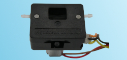
RV-001 Pinch Valve photo
Exterior photo
with an option tube
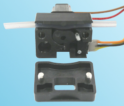
RV-001 Pinch Valve photo removing the cover
When the cover was removed
(Insert normal tube)
  • Ultra-low power consumption pinch valve
    ◦Power is supplied only when opening/closing, and
    power is not required to maintain the open/closed
    state. Therefore, almost no heat is generated.
    ◦A DC geared motor is used for drive, making the
    configuration simple and eliminating the need for a
    dedicated drive circuit.
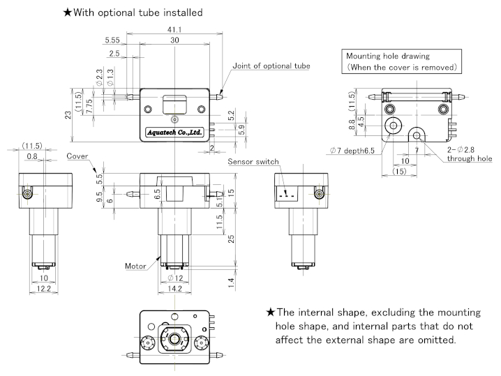
  • The main unit is small and lightweight, with dimensions (W x D x H) of 30 x 23 x 41.4 mm and weight approximately 33 g. (excluding wiring and tube)
  • The cover is attached with a magnet, so tube replacement is easy.
  • We sell an optional special tube with joiners on both ends that can be easily attached to the valve.
  • The optional RE-V100 dedicated controller is available, which allows you to individually program the operation sequences of the three valves.
Download
Catalog (PDF)
(Controller included)
Outline drawing (PDF)
3D CAD data (STEP)
2D CAD data (DXF)


Standard model / Model No. & Specifications
Valve model No. Wiring length Connector of wiring
RV-001ZA 50 cm Without connector
RV-001ZB 2 m With connector
RV-001ZC 50 cm With connector
  • Tubes are not included.
  • Use tubes with the following dimensions as listed in the "Suitable Tubes" table below.
      ◦TM-15 : ID 1.6 mm x OD 3.2 mm
      ◦Others : ID 1/16 inch (1.59 mm) x OD 1/8 inch (3.18 mm)
  • When using the motor controller RE-V100, it is necessary to use the valve indicated "With connector".
Standard model / Common Specifications
Item Specification
Rated voltage DC 3V
Fluid pressure 0 to 150 kPa
Valve opening/closing time 0.3 sec or less
Pumping volume 5 µL or less
Tube durability Over 150,000 cycles
Durability of the drive system Over 500,000 cycles
Suitable Tubes
Tube name Manufacturer Remarks
Single-Use Silicone Tube
Type V:High Durability Grade
Shin-Etsu Polymer Co., Ltd. Silicone rubber,
USP Class VI
PharMed BPT Saint-Gobain Thermoplastic elastomer,
USP Class VI
Versilon F-5500-A Saint-Gobain Fluoroelastomer
Transmaster TM-15 Mitsuboshi Co., Ltd. Olefin-based
TYGON LMT-55 Saint-Gobain Polyvinyl chloride resin,
DEHP free
  • Use tubes with the following dimensions as listed in this table.
      ◦TM-15 : ID 1.6 mm x OD 3.2 mm
      ◦Others : ID 1/16 inch (1.59 mm) x OD 1/8 inch (3.18 mm)
Sterilization of suitable tubes
Tube name Sterilization Method
Autoclave
121°C 25 min
EOG sterilization Gamma ray sterilization
25 kGy or less
Single-Use Silicone Tube
Type V:High Durability Grade
Yes Yes Yes
PharMed BPT Yes Yes Yes
Versilon F-5500-A Unconfirmed Unconfirmed Unconfirmed
Transmaster TM-15 No Yes Yes
TYGON LMT-55 No Yes Yes
Optional Tubes
Optional Tube model No. Tubes used Remarks
AR-TBS1.6×3.2-K Single-Use Silicone Tube
Type V:High Durability Grade
Silicone rubber,
USP Class VI
AR-TBF1.6×3.2-K PharMed BPT Thermoplastic elastomer,
USP Class VI
AR-TBR1.6×3.2-K Versilon F-5500-A Fluoroelastomer
AR-TBW1.6×3.2-K Transmaster TM-15 Olefin-based
AR-TBD1.6×3.2-K TYGON LMT-55 Polyvinyl chloride resin,
DEHP free
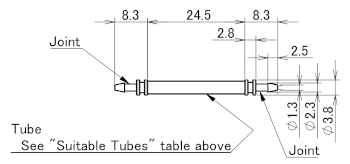
  • The optional tube is a 24.5mm long suitable tube with special joints attached to both ends. And it can be easily attached to the valve.
  • Optional tubes are sold in units of 10. The above model numbers are for a set of 10.

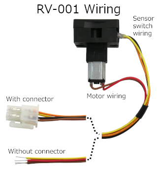
RV-001 Wiring
  • There are five wires coming out of the valve, as shown in the photo to the left.
    There are two types of wire end process:
      ◦With connector
      ◦Only the insulation is stripped
            (Without connector)
  • The length of the wiring is as shown in the "Standard model / Model No. & Specifications" table.
  • The connector is for connecting to the motor controller RE-V100.
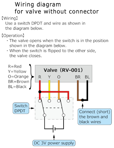
  • The valve without connector can be operated by wiring as described below.


RV-001 wiring without connector
{ Wiring }
  • Prepare a switch DPDT and a 3V DC power supply (DC power supply, dry cell, etc.).
  • Connect the five wires coming out of the valve (red, orange, yellow, brown, and black) as shown in the diagram on the left.
        
{ Operation }
  • When the switch is in the position shown in the diagram (red is positive, orange is negative), the valve opens.
  • When the switch is in the opposite position to that shown in the diagram (yellow is positive, red is negative), the valve is closed.


Outline drawing
Outline drawing
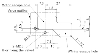
Mounting holes
Mounting holes drawing
Outline of ptional Tubes
Optional tube outline


For Ultra-low power consumption pinch valve RV-001 series
Programmable motor controller RE-V100